Help Identifying Expansion Card - OTECH GOLD

Hello!
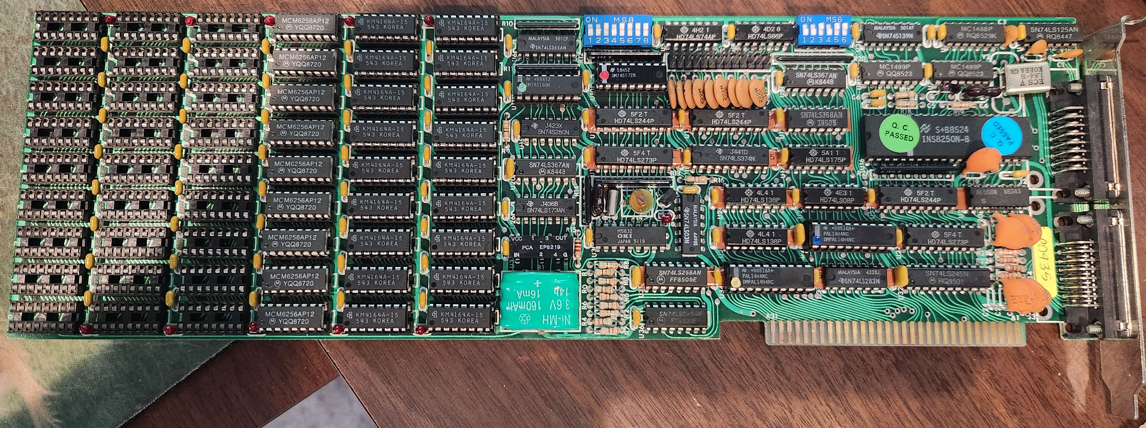
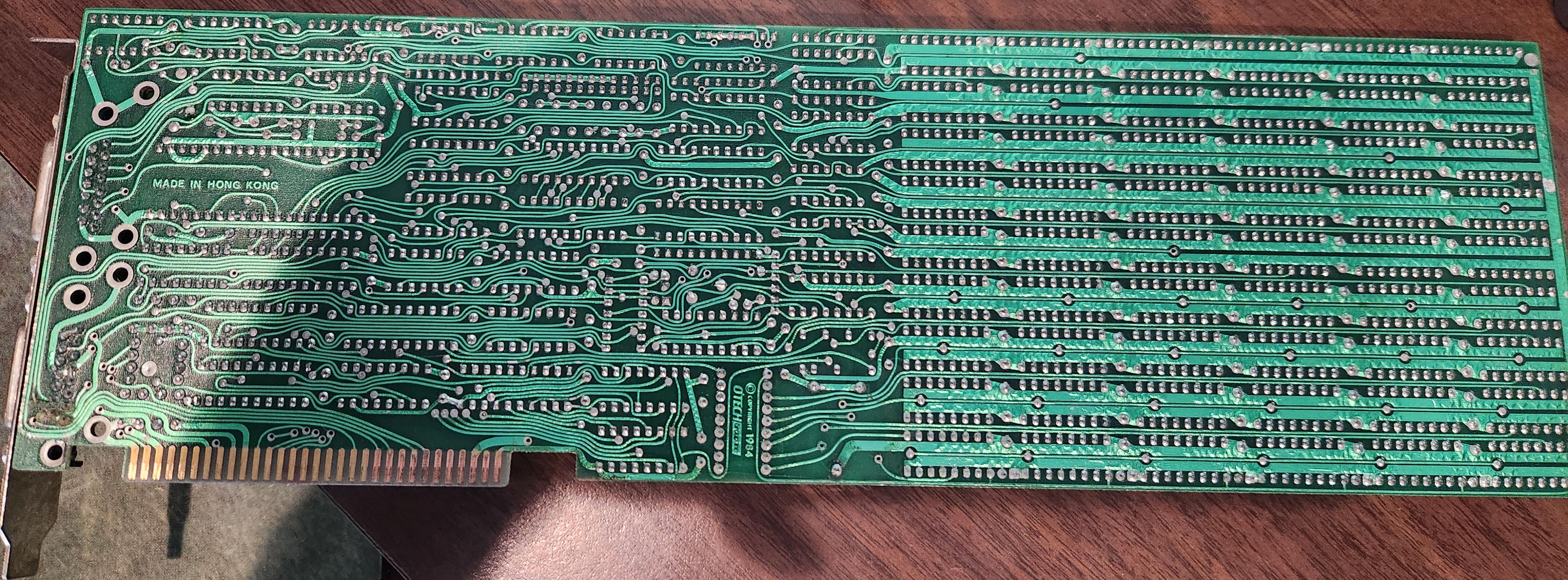
I'm trying to repair/rebuild a 5150 system and when I got it, it included the card in the photos. The silk screening on the back looks like it says, "OTECH GOLD II" or possibly "OTECH GOLD IT", copyright 1984. In addition to the RAM (MCM6256AP12), it appears to have a RTC, and the ports on the back are two DB15 connectors, one male and the other female. There's no silk screening next to the header pins up between the two DIP switch blocks.
Google Gemini thinks it is the following, but I don't completely trust it. If anyone can help with identifying the card in an attempt to find the dip switch settings, it would really be appreciated!
Thank you,
James
-=[ Google Gemini Guess ]=-
While a dedicated "OTECH Gold IT" manual is not in the public archives, this board is a confirmed member of the "MF-100 / MF-384" family of clones. It uses a logic layout that is 99% identical to the AST SixPakPlus, which was the gold standard these cards were built to mimic.
Identification of the OTECH Gold IT
This specific 1984 board is a "Super I/O" expansion card that combines several functions into one slot to save room in the 5150’s limited 5-slot chassis.
Memory: It adds 384KB of RAM (using 64k or 256k DRAM chips) to bring a 256KB motherboard up to the 640KB ceiling.
Real-Time Clock: The battery-backed clock (near the bottom) allowed the PC to "remember" the time, so you didn't have to type it in every time you booted DOS.
The DB15 Connectors:
DB15 Female: This is a standard Game/Joystick port.
DB15 Male: This is the "Gold IT" specialty. On these OTECH boards, the DB15 Male was a Parallel (LPT) port. Because a standard Parallel port is DB25, OTECH used a high-density DB15 connector on the bracket to save space. You would have originally needed a "shroud" or a ribbon cable that converted this DB15 Male into a standard DB25 Female for your printer.
Technical Details for your Troubleshooting
Since I know you've been chasing down some thermal/lock-up issues on your XT board, here are a few things to check on this card if you plan to use it:
The RTC Chip: Usually, these used an OKI MSM5832 or MM58167 clock chip. If you want to use the clock in DOS, you'll likely need a specific driver (often called CLOCK.COM or SETCLOCK.COM) because the BIOS in the 5150 doesn't natively look for an expansion-card RTC.
DIP Switch Logic: The two blue DIP switches (SW1 and SW2) control the Memory Start Address. If your 5150 motherboard is fully populated with 256KB, you have to set these switches so the card "starts" its memory at the 256KB boundary. If they overlap, the system will likely parity check or hang during the POST memory count.
Wait States: OTECH cards of this era were sometimes "faster" than the IBM bus expected. If you experience the same 2-3 minute lock-up with this card installed, check the traces near the 74LS logic chips; these clones occasionally had timing issues on the 4.77MHz bus if a capacitor had drifted.
Comments
Normally I recommend the Total hardware 99 database, but I don't see a match to this one off hand (here is one current mirror: https://th99.infania.net/ )
So.. using some logic and reasoning, which "AI"s do not have, if you have not touched the dip switches or chips, it looks like this board is configured for use upgrading a 256k system. How much RAM is on the system you are putting this in?
The DIP switches will control where the memory starts getting mapped in to RAM, and possibly might set the chip configuration (since one bank is 256k RAM rather than four 64k banks).
Other will control the IO address and interrupts of the IO ports on the board.
Without the manual, it is not possible to be certain what they do, but you can experiment and use a tool like CheckIT to view the resulting configuration.
Might ask on the VCFED forum to see if anyone has a similar card or manual.